Mars Rover Robotic Arm 2020
Project Role: Team Lead
Northeastern's Mars Rover Competition Team is dedicated to contending in the University Rover Challenge. The challenge? "Design and build the next generation of Mars rovers that will one day work alongside human explorers in the field." I am currently leading the team of 5 senior engineering students devoted to designing the rover's robotic arm.
Problem Statement
Design and build a lightweight, low cost, durable, and maneuverable robotic arm to perform the extreme retrieval and equipment servicing tasks for the University Rover Challenge.
Requirements and Constraints
-
Pick up, carry, and drop off 5 kg objects
-
Perform precise maneuvers (flip switches, turn knobs, etc)
-
< 10kg
-
< $4,000
-
Compatible with the rover's electronics and software
-
Remote controlled
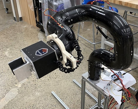
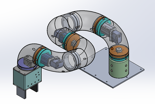
System Overview
-
5 Degrees of Freedom
-
Shoulder pitch and yaw
-
Elbow pitch
-
Wrist pitch and roll
-
-
Face-mounted actuation at joints
-
Rack and pinion gripper
-
Carbon Fiber members
-
Up coming:
-
Coiled cable routing
-
Camera mount at wrist
-
Gripper tools
-
Rack and Pinion Gripper
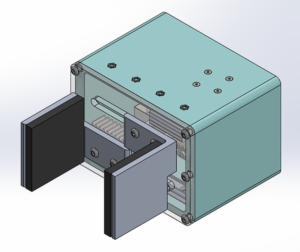
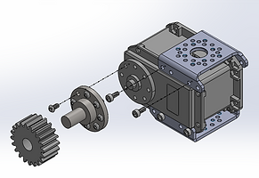
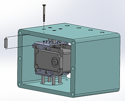
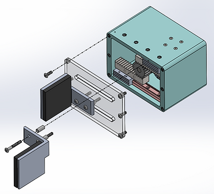
My largest contribution to the 2020 rover arm would be the gripper design. The fingers are driven by a rack and pinion system gliding on miniature carriage and rails. The frame is 3D-printed in Onyx with heat set inserts for bolting on an acrylic plate with slots. The assembly of this gripper can be seen below in the consecutive exploded views. I also analyzed these components to confirm the gripper will be capable of lifting up to 5 kg and the bolts would sustain infinite life calculations.
Gripper Assembly


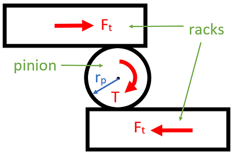
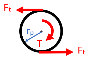
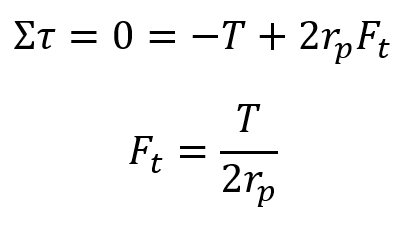
Force Analysis
To the right, you can see a diagram of the rack and pinon system. Below is a free body diagram of the pinion and the subsequent equations used to determine the force exerted onto the racks. By assuming that the force exerted onto the racks is the force that will be exerted by the fingers, I was able to determine the grip force necessary to hold 5 kg.


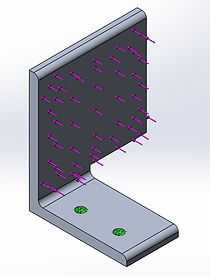
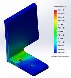
Component Strength Analysis
After determining the force necessary for gripping a 5 kg object, I then performed FEA on the fingers to ensure they would not fail. Additionally, I performed infinite life calculations on the bolts connecting the fingers to the racks and the racks to the carriages. The equations for these calculations can be seen below.
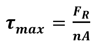

Variable definitions
τmax : Maximum shear stress on each bolt
FR : Shear force on all bolts
A : Tensile area of each bolt
n : Number of bolts
Se' : Endurance limit of bolts
nf : Factor of safety
Working Prototype